1. Industrial safety for formwork removal:
To ensure stability during construction phase, in addition to any other construction provisions, these recommendations should be followed:
Removal of formwork when concrete is fresh (concrete resistance to compression is greater than 1.5 MPa).
Resistance when fresh and stability of the external face is ensured by using plastic connectors to:
- Limit slenderness ratio of outer wall to values below traditional values. Distribution of plastic connectors at minimum rate of one per m² results in an effective height of the outer wall of 1 m. For a thickness of 8 cm, the slenderness ratio is then 13, which is lower than the slenderness ratio of a traditional wall.
- Ensure external face is attached to internal face to resist any out-of-plane loads before the effective connection using stainless steel tie bars. Appendix XX sets out the checks to be completed to ensure wind-induced load resistance after formwork is removed, if the resistance to compression of the concrete is greater than 1.5 MPa.
The plastic connectors also have a vital role in the stability of the external face when fresh and for the industrial safety of workers.
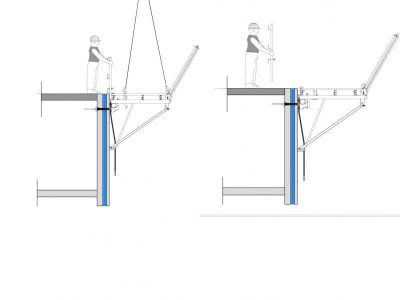
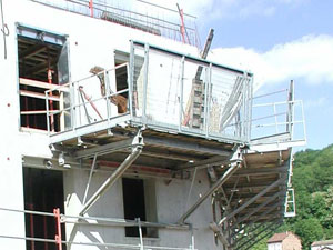
- Installation of work and security platforms:
The concrete must have a design-basis resistance to compression of 13MPa when the work and security platforms are installed on the floor above.
The equivalent of a ST25C lattice (i.e. 2.57 cm²/m per direction) must be positioned at the centre line of the external face; if wheel load incurred by stiffeners in work and security platforms of 5 kN/m, a void fraction (openings) of 50% and a height less than or equal to 180 cm between the spacers located immediately below and above the platform support bars is required. An explanation is attached in the Appendix providing details of the way in which worksite loads (work and security platform weights) are assessed and then applied to the faces.
The stability of the external wall is assured in the preliminary phase by the rigid connection created by the plastic spacers.
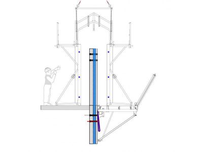
- Installation of a pipe or services sleeves during formwork of level 1 gable wall.
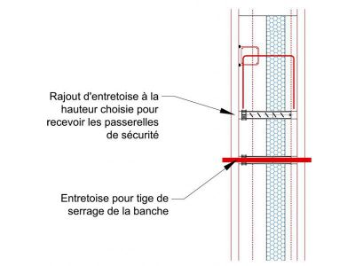
- After removal of the level 1 gable wall, install hooks to support platform in the pipe or services sleeves at the wall head.

- Construction of level 2 slab.
- Slinging of gable platform.
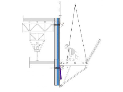
- Removal of support hooks.
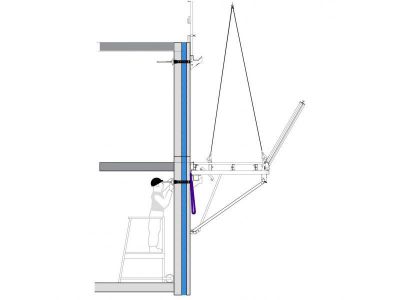
- Raising of platform. Recovery of support hooks. Towing cord attached to support hooks on platform.
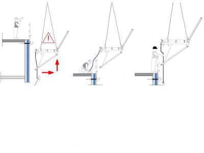
- Platform repositioned on support hooks, on next level.
- Formwork of gable wall. Concreting and then cycle resumed at next level.
Comments: always refer to requirements stipulated by manufacturers of work and security platforms and formwork. Appoint a handling lead to give instructions to crane operator.
2. Removal of formwork
- Install stabilizer blocks for the set of formwork panels for the next cycle.
- Loosen the end scales from the formwork.
- Loosen the tightening rods.
- Disconnect the formwork, if this is required for the lifting equipment .
- Loosen the struts at the bottom of the formwork.
- The first set of formwork panels to be removed is the one that was closed last.
- When the set of formwork panels has been stabilised, face to face, using cursor struts, formwork is removed and handled using slings with two equal strands (max. lifting capacity: 3T per strand).
- When the set of formwork panels has been stabilised, face to face, using self-stabilizer, formwork is removed and handled using lifting beam with spreader bars.
- Firstly remove an external formwork panel, then secure in place before removing next formwork.
- Check that the cast wall is totally free from contact with formwork:
- for metal formwork, remove rods and magnets;
- for wooden formwork, remove corners and mechanical fasteners (nails, screws, etc.);
- Check that the concrete wall is totally stable before formwork is fully removed;
- Remove formwork from jigs and pipe or service sleeves.
Comment: Always stabilize the wall before formwork is fully removed.
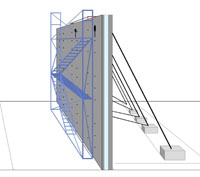
3. Behaviour under construction loads
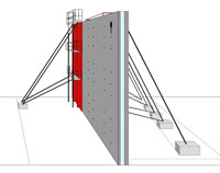
Walls built using the GBE System® are modelled as a beam with dimensions of 1000 x 80 mm², they are supported at the bottom and using plastic spacers.
Two possible configurations are studied to determine the maximum moment produced by supporting the work and security platform in the construction phase.
- Case A - work and security platform supported by spacer next to tightening rods.
- Case B - work and security platform bracket supported by spacer at wall head.
The span is slightly wider in case B (1.8 m).
The calculation is completed for concrete with a design compressive strength after 7 days (Fcd) of 13.3 MPa (it is recommended to apply a safety coefficient of 1.5 to Fck = 20 MPa to obtain the design compressive strength).
The wall support is considered to be a rigid point on the ground floor, which then becomes a hinge from level 1 onwards. In addition, the horizontal forces of 5 kN exerted on the face are doubled to take account of the singular points in the support area of the face (opening for window, for example). It is therefore 10 kN in this case.


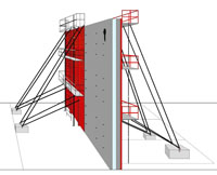
Figure 1: Design configurations for external face in construction phase.
The calculation data for lowering loads on the work and security platform is taken from technical document PTE SATECO 2 (see Figure 2 below).
The maximum force applied on the plastic spacers in the preliminary phase is approximately 12.3 kN (see Figure 3). The maximum strength obtained during mechanical testing of the spacers was Nmax = 32 kN (see Section 3.1 of mechanical test report of GBE System®), i.e. a design strength value of NRd = Nmax / 1.5 = 21 kN lower than the active force.

Figure 2: Lowering loads on work and security platform / Figure 3: Reactions Rx in external face during construction phase.
4. Finishing on formwork holes
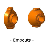
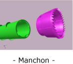
- Remove the end pieces (orange) from the spacers and from the sleeves (pink), apart from in locations where the spacers are designed to support the work and security platform.
- Protect the Bidim wall before assembling the work and security platform.
- Fill any holes left by the spacers using:
- Insulation such as polyurethane foam to ensure continuity of insulations.
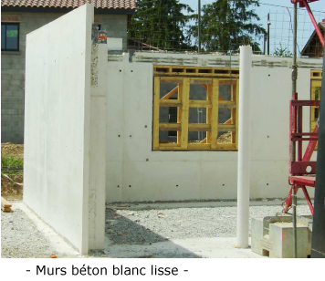
- Concrete skin (on external face). Skins vary depending on the colour of the wall.
- Concrete plugs prefabricated in special moulds, depending on colour of concrete, can be used on external face.
- Concrete skin (on external face).
- Transition to following cycle.
- Clean and lubricate the form-lining faces.
Observations: Suspend all work in event of strong winds.


